- All
- Product Name
- Product Keyword
- Product Model
- Product Summary
- Product Description
- Multi Field Search
English

Views: 0 Author: Site Editor Publish Time: 2026-07-30 Origin: Site
Choosing the wrong hydraulic motor type leads to compounded energy losses, excessive heat generation, and premature system failure. The engineering and commercial stakes run high when designing heavy-duty fluid power systems. Engineers must prioritize reliable components to guarantee continuous machine operation. A Fixed Displacement Hydraulic Motor operates on a fundamental and predictable mechanical premise. Every shaft revolution consumes a constant, unchangeable volume of pressurized hydraulic fluid. This guide provides system designers and procurement specialists an evidence-based framework for confident component selection. You will learn to evaluate, specify, and implement these robust motors effectively. We explore underlying mechanics, application matching, and the distinct advantages they offer over variable alternatives.
Predictable Performance: Fixed displacement hydraulic motors deliver a constant torque and speed proportional to input flow and pressure, making them highly reliable for continuous-duty applications.
Cost vs. Complexity: They offer a lower initial capital expenditure and simplified control architecture compared to variable displacement motors, though they sacrifice adaptive efficiency in fluctuating load scenarios.
Selection Imperative: Successful implementation requires exact matching of motor displacement ($cm^3/rev$) to system flow capacity and operating pressure limits—oversizing wastes energy, while undersizing causes catastrophic wear.
Risk Mitigation: The most common failure modes stem from poor thermal management, incorrect fluid viscosity, and inadequate filtration, rather than mechanical design flaws.
You must understand the baseline mechanics to specify fluid power components correctly. A Fixed Displacement Hydraulic Motor features an internal geometry that never changes. Every complete rotation consumes a specific, immutable volume of hydraulic fluid. The system flow rate directly dictates the output rotational speed. Meanwhile, system operating pressure strictly governs the output torque. These motors cannot independently adapt to varying loads. They strictly translate hydraulic power into mechanical power based on incoming fluid parameters.
Engineers categorize these motors into three structural designs. Each topology serves different industrial requirements. You should match the design to your target performance metrics.
Gear Motors: They offer a highly cost-effective and robust design. You will find them ideal for lower pressure and lower speed applications. They handle fluid contamination better than other types.
Vane Motors: They provide mid-range mechanical efficiency. Vane designs excel in medium-pressure environments. They generate significantly lower noise levels during operation.
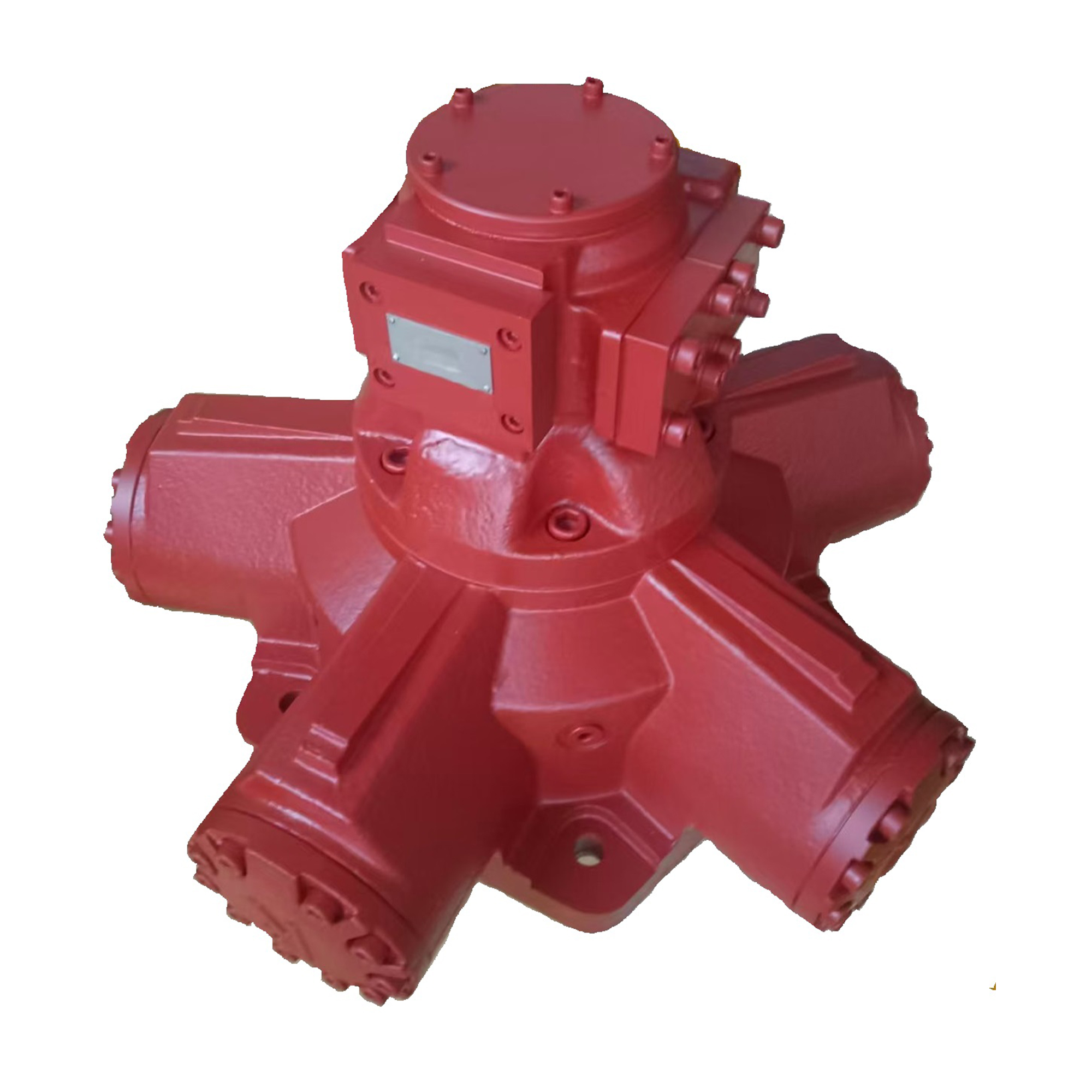
Piston Motors (Radial & Axial): They deliver exceptional volumetric efficiency. You use them for high-pressure systems. They suit heavy-duty industrial and mobile machinery perfectly.
Motor Topology | Relative Efficiency | Pressure Tolerance | Primary Advantage |
|---|---|---|---|
Gear Motor | Low to Medium | Low to Medium | High durability and low upfront cost |
Vane Motor | Medium | Medium | Quiet operation and smooth rotation |
Piston Motor | High | High | Maximum power density and efficiency |
Engineers often assume ideal conditions during preliminary calculations. A fixed designation never implies 100% mechanical efficiency. Internal fluid leakage always occurs. We call this internal slippage. Slippage increases proportionately as operating pressure rises. Component wear over time also increases this leakage rate. You must factor this volumetric loss into your designs. Slippage directly reduces the actual output speed compared to theoretical calculations. Experienced designers always compensate for these expected losses during the sizing phase.
System designers face a classic engineering dilemma. You must justify the higher investment of variable displacement units against the proven reliability of a Fixed Displacement Hydraulic Motor. The decision hinges on application variability. Variable motors adapt to changing load demands continuously. Fixed units deliver uncompromising, steady-state performance. You need to weigh operational predictability against the need for dynamic system flexibility.
Fixed displacement units provide a significantly lower initial capital expenditure. They contain fewer moving parts. They lack complex internal swashplates or pivoting mechanisms. This simplicity directly translates to easier maintenance routines. Your technicians require less specialized training to service them. Conversely, variable displacement units demand higher upfront capital. They utilize complex servo-controls. These advanced controls require specialized diagnostics and frequent calibration.
Control strategies differ fundamentally between the two motor types. A fixed displacement unit relies entirely on external valving. You must install directional valves to manage rotation. You must use external flow control valves to govern motor speed. The motor itself remains entirely passive regarding flow regulation. Variable motors house internal control mechanisms. They adapt their displacement autonomously based on pressure feedback. This internal adaptation reduces the need for complex external valve manifolds.
You must acknowledge specific limitations when specifying fixed displacement technology. These units operate optimally at their maximum designed load. Running them at partial loads introduces system inefficiencies. The pump supplies a constant flow regardless of the load requirement. You must route unneeded flow across a system relief valve. This bypass process generates significant heat. Variable motors avoid this issue. They optimize their internal power draw. They only consume the exact fluid volume required for the immediate task.
You can establish a reliable rule of thumb for component matching. Fixed displacement components thrive in environments demanding continuous operation. They excel when you require predictable, single-speed rotation. You should specify them for applications operating under relatively stable load conditions. If your application rarely experiences sudden torque spikes, fixed designs provide maximum longevity.
Factory environments provide the perfect ecosystem for these motors. Conveyor belt drives require constant, unwavering torque. Industrial mixers need continuous rotation speeds to process materials evenly. Machine tool spindle drives demand rigid predictability. System parameters in manufacturing plants remain highly controlled. A Fixed Displacement Hydraulic Motor delivers the exact non-negotiable torque required for these automated processes.
Harsh outdoor environments test mechanical durability severely. Agricultural harvesters and construction excavators rely on rugged components. Winch drives demand raw, continuous pulling power. Engine cooling fan drives require steady rotational speeds. You will find fixed units driving specific propulsion circuits in heavy machinery. Mechanical durability outweighs the need for micro-adjustments. Their robust housings withstand severe vibration and external impacts seamlessly.
Certain industries impose strict regulatory standards. Mining and offshore drilling prioritize fail-safe mechanical behaviors. Fixed motors offer highly predictable mechanical responses. Complex electronic-variable systems can fail unpredictably during power loss. Fixed mechanical geometries align better with stringent compliance standards. Operators know exactly how the machinery will behave if external controls fail. This predictability ensures personnel safety in hazardous work zones.
Proper sizing requires a strict adherence to mathematical formulas. You can follow an actionable decision tree to size components accurately. This structured logic prevents costly field failures.
Calculate Torque Requirements: Evaluate both starting torque and running torque. Breakaway torque always exceeds continuous running torque. You must size the motor to overcome initial mechanical friction safely.
Determine Operating Pressure ($Delta P$): Identify the maximum available system pressure. Distinguish clearly between continuous pressure limits and intermittent peak pressure ratings.
Match Flow Rate to Speed: Calculate the exact fluid requirement. Determine the necessary Gallons Per Minute (GPM) or Liters Per Minute (LPM) based on your target RPM.
Engineers often make critical errors during the specification phase. Following strict design constraints ensures system longevity.
Do: Account for realistic mechanical efficiencies. Assume an 80-90% efficiency rate during initial calculations. Never assume an ideal 100% transfer of power.
Do: Verify the shaft side-load capacity if using belt or chain drives.
Don't: Rely on fixed motors for dynamic braking. You must integrate proper external counterbalance valves to stop heavy loads safely.
Don't: Undersize the motor to save upfront costs. This mistake guarantees rapid internal wear and catastrophic failure.
The motor cannot function independently of its power source. You must evaluate the existing hydraulic power unit carefully. Ensure the main hydraulic pump can supply the strict flow requirements. Failing to supply adequate fluid induces vacuum conditions. The motor will attempt to draw more fluid than the pump can push. This scenario causes severe system degradation. Always verify the pump flow curve against the motor consumption curve.
Fixed displacement designs lack internal flow regulation capabilities. You must manage excess fluid externally. When system demand drops, excess flow rushes over a pressure relief valve. This fluid shearing action generates massive thermal energy. Hydraulic oil degrades rapidly when subjected to extreme heat. You must incorporate adequate cooling systems. Specify properly sized air-to-oil or water-to-oil heat exchangers. Maintain fluid temperatures within the manufacturer's specified operating windows.
Overrunning loads present a severe risk to fixed motors. This occurs when a heavy mechanical load drives the motor shaft. The motor suddenly turns faster than the pump can supply fluid. A vacuum forms inside the motor inlet port. This vacuum pulls dissolved air out of the fluid. The resulting air bubbles collapse violently under pressure. This causes destructive cavitation. You must install anti-cavitation check valves. They allow the motor to draw fluid directly from the reservoir during overrunning conditions.
Fluid cleanliness directly impacts component lifespan. Different motor topologies exhibit varying tolerances to particle contamination. You must adhere to specific ISO cleanliness codes.
Gear Motors: Highly tolerant of contamination. Typically require ISO 21/19/15 filtration levels.
Vane Motors: Moderately sensitive. Usually demand ISO 19/17/14 fluid cleanliness.
Piston Motors: Extremely sensitive due to tight internal clearances. They strictly require ISO 17/15/12 or cleaner fluids.
Procurement professionals must vet component manufacturers thoroughly. Do not base purchasing decisions on price alone. Request comprehensive performance curves from the engineering department. Verify the difference between their continuous and intermittent pressure ratings. Check their supply chain reliability for replacement seals and wear parts. A cheap motor becomes exceptionally expensive if replacement parts require a six-month lead time. Partner with manufacturers who provide transparent engineering data.
A fixed displacement hydraulic motor remains the ultimate solution for predictable machinery. They excel in continuous-torque applications where simplicity and durability hold priority. They eliminate unnecessary electronic complexity. They survive in harsh environments where variable units fail. Evaluators must remember a critical strategic principle. Cost savings on the motor component should never compromise system efficiency. Poor integration leads to excessive heat generation and wasted power. You must balance component costs against proper system design. We recommend consulting directly with a certified fluid power engineer. Request a detailed sizing calculation for your specific machinery. Download technical selection datasheets to begin your specification process today.
A: Yes, but only externally. Speed is controlled by regulating the flow of hydraulic fluid to the motor using proportional or flow control valves, or by utilizing a variable displacement pump at the power source.
A: Torque loss is typically a symptom of internal wear (increasing internal leakage/slippage), fluid degradation, or a drop in system pressure from a failing pump.
A: Displacement is calculated by dividing the required fluid flow rate by the target RPM, factoring in the motor's specific volumetric efficiency rating. (Displacement = Flow / RPM * Efficiency).
A: Yes, they are frequently used in closed-loop hydrostatic transmissions, typically paired with a variable displacement pump to dictate speed and direction while the motor provides consistent torque translation.