- All
- Product Name
- Product Keyword
- Product Model
- Product Summary
- Product Description
- Multi Field Search
English

Views: 0 Author: Site Editor Publish Time: 2026-06-15 Origin: Site
Selecting or troubleshooting a hydraulic motor requires moving beyond basic catalog specs to understand how system variables interact in the real world. You must bridge the gap between paper calculations and actual machine behavior. Miscalculating motor speed leads directly to system inefficiency, excessive heat generation, or premature equipment failure. These errors create major friction during the decision stage for engineers and buyers.
Operating a machine with incorrect speed parameters stresses every component in your hydraulic circuit. You cannot simply install a unit and expect it to perfectly match its theoretical rating under heavy loads. Real-world physics always intervenes.
The purpose of this article is to provide a technical evaluation framework. We will explore exactly how flow rate, displacement, and efficiency dictate the speed of a hydraulic motor. By mastering these concepts, you can specify the correct component for your application, ensuring optimal performance and reliability.
The theoretical speed of a hydraulic motor is dictated by two primary factors: the input flow rate (gallons per minute or liters per minute) and the motor's displacement (volume per revolution).
Real-world rotational speed (RPM) is always lower than theoretical speed due to volumetric efficiency losses, primarily driven by internal leakage (slip).
Increasing a motor's speed without adjusting the system's power input will inherently decrease available torque.
Evaluating between fixed-displacement and variable-displacement motors depends heavily on the application's need for dynamic speed control versus upfront budget constraints.
Understanding motor speed begins with basic fluid dynamics. You must look at the mathematical relationship between how much fluid enters the system and how much space it needs to fill. This relationship gives you a theoretical baseline for performance.
The standard industry formula for calculating theoretical motor speed is straightforward. You calculate it using this exact equation: RPM = (Flow Rate × 231) / Displacement. The number 231 represents the cubic inches in one U.S. gallon. If you work in metric units, you use a slightly different formula: RPM = (Liters Per Minute × 1000) / Displacement in cc/rev. These formulas tell you how fast the shaft will turn under perfect, zero-loss conditions.
Think of the primary pump's output volume as the accelerator pedal for your motor. The flow rate dictates the speed. When you increase the gallons per minute (GPM) or liters per minute (LPM) entering the motor, you force the internal components to rotate faster to process that fluid. Without sufficient flow, high speeds are physically impossible. You must size your primary pump correctly to achieve your target RPM.
Displacement represents the exact physical space inside the motor. It is the specific volume of fluid required to complete one full mechanical revolution. Manufacturers express this rating in cubic inches per revolution (in³/rev) or cubic centimeters per revolution (cc/rev). A motor with a displacement of 5 in³/rev must consume exactly 5 cubic inches of pressurized fluid to turn the output shaft 360 degrees once.
Flow and displacement share an inverse relationship when you calculate speed. If you maintain a constant, fixed flow rate from your pump, changing the displacement changes the speed dramatically. A smaller displacement motor fills up faster, causing it to spin at a much higher RPM. Conversely, a larger displacement motor takes longer to fill. It will spin much slower using that exact same flow rate. You must balance these two variables carefully.
Theoretical math provides a great starting point. However, mechanical reality paints a different picture. No fluid power system operates at 100% efficiency. You must account for physical losses to accurately predict how fast your machine will run in the field.
Bench-tested RPM rarely matches the installed RPM on a working machine. Theoretical speed assumes every single drop of fluid pushes the motor's gears, vanes, or pistons. In reality, physical tolerances and moving parts allow fluid to escape. If your math predicts 1,000 RPM, but your motor has an 85% volumetric efficiency rating, you will only achieve roughly 850 RPM. You must always design systems using actual speed projections, not theoretical maximums.
We use the term "slip" to describe internal leakage. A certain percentage of hydraulic fluid always bypasses the motor's driving mechanisms. It sneaks through the tiny clearances between gears and housings or pistons and cylinder blocks. This fluid travels straight to the return line or case drain without doing any mechanical work. Because this bypassed fluid fails to rotate the shaft, you experience a direct drop in operational speed.
System pressure heavily influences how much slip occurs. Pressure represents resistance to flow. When you apply a heavy mechanical load to the motor shaft, system pressure spikes. This high pressure aggressively forces more fluid through the internal clearances. As leakage increases under heavy loads, your volumetric efficiency plummets. This explains why a motor spins slower when lifting a heavy weight compared to spinning freely in the air.
Fluid conditions also dictate your actual speed. Hydraulic oil changes viscosity based on temperature. As your machine works, friction generates heat. High operating temperatures cause the fluid to thin out. Thin fluid slips through internal gaps much easier than thick, cold fluid. This exacerbates slip and further degrades your volumetric efficiency over time. You must maintain proper cooling systems to keep fluid viscosity stable and motor speeds consistent.
Different internal designs handle flow, pressure, and leakage differently. You must match the mechanical architecture of the motor to your target speed and load requirements. Below is a breakdown of the three primary architectures.
Gear designs utilize meshing gear teeth to drive the output shaft. They represent the simplest and most common technology in fluid power.
Best applications: They excel in high-speed, low-torque applications like running fan drives or light conveyors.
Performance characteristics: They offer a lower initial cost but suffer from lower volumetric efficiency. Because the internal clearances are relatively large, gear designs experience high slip. Their speed drops significantly when you apply heavy loads.
Vane designs use sliding rectangular vanes pushed outward against a cam ring by internal springs or fluid pressure.
Best applications: They provide mid-range speeds and operate much quieter than gear types. Engineers often specify them for applications requiring smooth, continuous rotation at moderate speeds.
Performance characteristics: Vane types feature better volumetric efficiency than gear types. The vanes physically wear into the cam ring, maintaining a tight seal over time. This keeps slip relatively low until the vanes require replacement.
Piston designs use reciprocating pistons inside a cylinder block. They represent the highest tier of performance and efficiency.
Axial piston motors: These arrange pistons parallel to the shaft. They are capable of very high speeds and extremely high operating pressures. They offer excellent volumetric efficiency, often exceeding 95%.
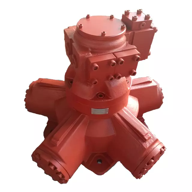
Radial piston motors: These arrange pistons perpendicular to the shaft, like spokes on a wheel. They are specifically designed for low-speed, high-torque (LSHT) applications. They handle massive loads without stalling.
Decision lens: Piston units require a premium upfront budget. However, you absolutely need them for precise speed control, rigorous duty cycles, and heavy industrial applications.
Motor Type | Speed Range | Torque Capacity | Volumetric Efficiency |
|---|---|---|---|
Gear | Medium to High | Low to Medium | Low (70% - 85%) |
Vane | Medium | Medium | Moderate (80% - 90%) |
Axial Piston | High | Medium to High | High (90% - 95%+) |
Radial Piston | Low (LSHT) | Very High | Very High (90% - 95%+) |
You cannot discuss speed without discussing torque. These two forces oppose each other within the boundaries of your available hydraulic horsepower. You must understand this trade-off to size your system correctly.
Speed, torque, and total hydraulic horsepower are locked in a mathematical relationship. If you have a fixed amount of horsepower from your power unit, you face a strict compromise. You can have high speed or high torque, but you cannot have both simultaneously. If you increase the speed of a hydraulic motor without increasing the primary pump's output power, your available twisting force drops proportionally.
Prioritizing maximum RPM severely limits the motor's ability to move heavy loads. If you select a very small displacement motor to achieve 3,000 RPM, it will stall easily under resistance. To overcome this, you would have to simultaneously increase system flow and system pressure, which requires a much larger prime mover (electric motor or diesel engine). You must size your components based on the heaviest load your machine will encounter.
You need a framework for deciding which variable takes priority. Look at the specific task. Fan drives and centrifugal pumps require high speed and very low torque. You prioritize RPM here. Winches, excavators, and heavy conveyors require massive pulling force at slow speeds. You prioritize torque and accept a lower RPM. Identify your success criteria before you select a displacement size.
Once you install a motor, you often need to adjust its speed during operation. You can achieve this using several different mechanical and electrical methods. Each method carries specific benefits and drawbacks.
Flow control valves act as restrictive bottlenecks in the hydraulic line. They limit the amount of GPM reaching the motor.
They are highly cost-effective and easy to install.
They restrict fluid or bypass excess fluid over a system relief valve.
They generate significant heat due to this restriction.
They are best suited for simple, low-duty systems where exact precision is not mission-critical.
Instead of restricting flow, variable displacement motors change their own internal geometry. They typically use an adjustable swashplate.
This allows operators to change the displacement on the fly to alter speed.
You do not waste system flow over a relief valve, meaning you generate far less heat.
When you angle the swashplate for less displacement, speed increases but torque drops.
They are ideal for complex mobile equipment and heavy industrial machinery requiring high efficiency.
You can control the speed of the fluid power system electrically. A VFD regulates the speed of the electric motor driving the primary hydraulic pump.
By slowing down the electric motor, the pump pushes fewer GPM into the circuit.
This is the most energy-efficient solution available today.
It reduces overall wear and tear on both the pump and the hydraulic motor.
It is highly recommended for stationary industrial applications.
Modifying the speed of an existing system carries engineering risks. Pushing components outside their intended operating parameters causes rapid degradation.
Over-Speeding (Cavitation and Wear): Pushing a motor beyond its rated RPM is dangerous. It leads to inadequate internal lubrication. More critically, it causes cavitation. When the motor tries to pull fluid faster than the pump can supply it, vapor bubbles form and violently collapse. This tears metal away from internal plates and causes catastrophic internal failure.
Under-Speeding (Cogging): Running motors at extremely low speeds presents a different challenge. Unless you use a dedicated Radial Piston LSHT unit, running standard units too slow causes a phenomenon known as cogging. The shaft rotates in a jerky, inconsistent manner instead of a smooth sweep. This damages driven mechanical loads.
Thermal Overload: Using restrictive flow control valves to dramatically lower speed forces excess fluid over relief valves. This pressure drop creates severe friction. It generates system-killing heat, thins out the oil, and rapidly degrades fluid life. You must monitor system temperatures if you restrict flow extensively.
Hydraulic motor speed represents a delicate balance between rigid physics and unpredictable real-world conditions. You calculate theoretical speed using flow and displacement. However, you must always account for internal leakage, pressure spikes, and volumetric efficiency losses to determine actual field performance. Ignoring these factors leads to underperforming machines.
We advise against sizing a motor based on theoretical speed alone. Always factor in your minimum torque requirements and your worst-case volumetric efficiency. Understand that maximizing speed inherently sacrifices pulling force unless you increase total horsepower.
Your next step should be gathering exact operational data. Consult with a fluid power specialist or utilize advanced system sizing software. These tools help you match the exact motor type, displacement, and efficiency rating to your specific application's load profile, ensuring long-term reliability.
A: No. System pressure strictly dictates the motor's torque, which is its pulling or twisting force. The input flow rate dictates the speed. In fact, increasing system pressure can sometimes slow a motor down because high pressure increases internal leakage, which lowers your volumetric efficiency.
A: A heavy load requires more mechanical force, generating higher pressure within the circuit. This increased pressure forces more hydraulic fluid to slip past the internal clearances of the motor rather than doing work. This loss of volumetric efficiency results in a noticeable loss of actual RPM.
A: It is not recommended unless the unit is specifically designed as a Low-Speed, High-Torque (LSHT) motor. Standard gear or vane motors will experience "cogging" at low RPMs. This creates jerky, inconsistent shaft rotation and can lead to complete stalling under even moderate loads.