- All
- Product Name
- Product Keyword
- Product Model
- Product Summary
- Product Description
- Multi Field Search
English

Views: 0 Author: Site Editor Publish Time: 2026-09-13 Origin: Site
Heavy-duty 2026 industrial and mobile machinery projects demand high power density and reliable low-speed, high-torque (LSHT) rotary actuators. Engineers face a persistent challenge balancing continuous high-torque performance requirements with strict spatial constraints, thermal management limits, and harsh environmental operating conditions. Equipment like marine winches, mining crushers, and industrial shredders cannot tolerate unexpected downtime or sluggish response times under heavy loads.
This guide serves as the definitive framework for evaluating the CA100 hydraulic motor against your specific project specifications. We will examine alternative displacements, mechanical configurations, and system integration requirements. You will learn how to match the precise torque output to your duty cycle, ensuring your procurement decisions align with long-term operational stability and machine efficiency.
Identify exact continuous and peak torque requirements to validate the CA100 against alternative radial piston configurations.
Decode standard manufacturer nomenclature to specify exact shaft types, port connections, and displacement variations.
Assess the total physical footprint, shaft specifications, and mounting configurations to ensure seamless machine integration.
Factor in fluid viscosity requirements, cooling demands, and maintenance intervals to accurately project lifecycle performance.
Evaluate supplier reliability, warranty terms, and projected 2026 supply chain lead times before finalizing vendor selection.
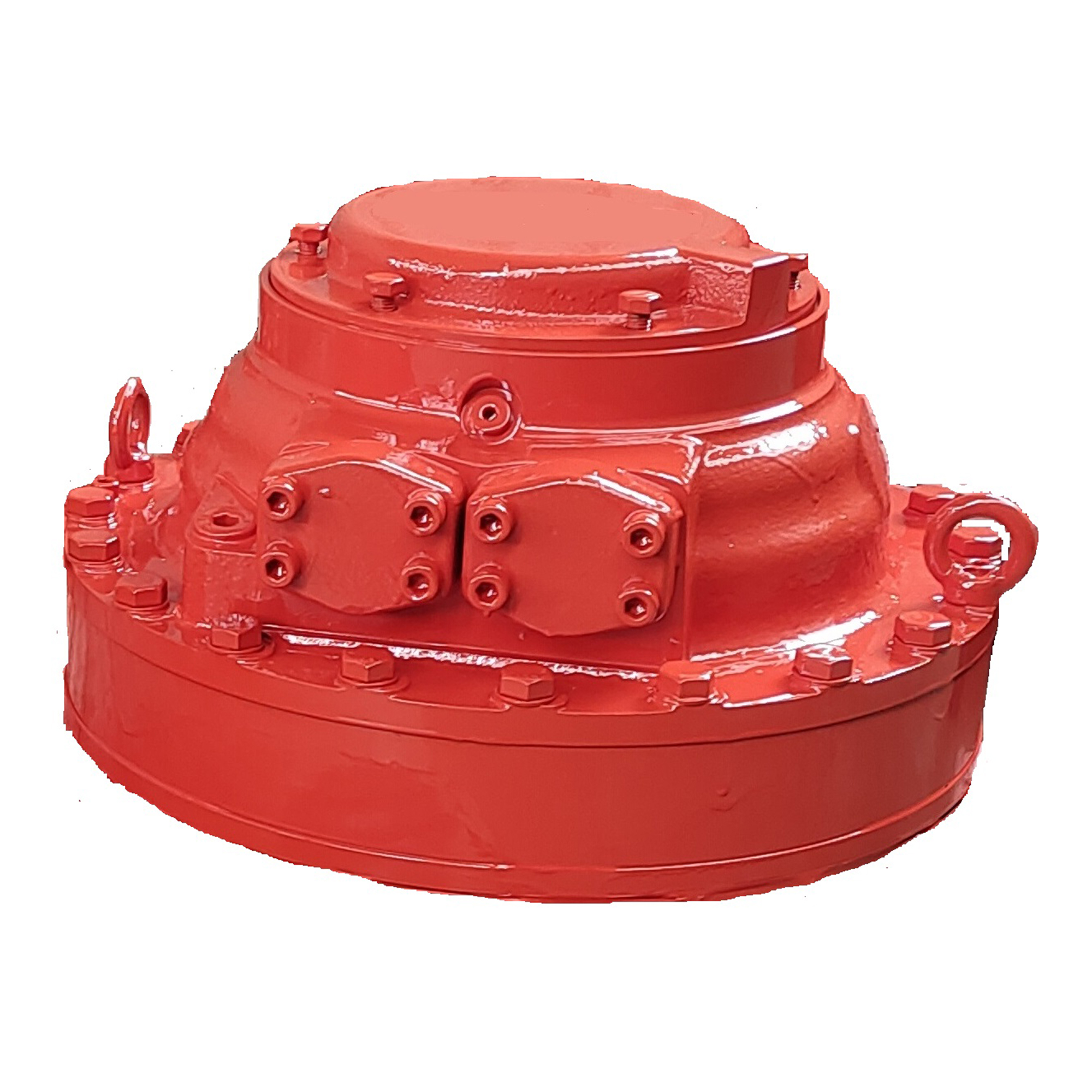
Radial piston mechanics provide exceptional torque-to-weight ratios. The design relies on a stationary cylinder block and a rotating cam ring. Hydraulic fluid enters the cylinder block under high pressure through a central distributor valve. This fluid pushes the pistons outward. The rollers at the end of the pistons press against the multi-lobe cam ring. The reaction force between the rollers and the cam profile generates rotational torque. Because the cam ring features multiple lobes, each piston performs several power strokes per revolution. This mechanical advantage allows the Cam Lobe Hydraulic Motor to produce massive torque at very low rotational speeds without requiring a reduction gearbox.
Heavy industries rely heavily on this energetically dense motor profile. Marine winches require constant tension control to manage heavy loads against unpredictable ocean swells. The motor must hold the load securely and rotate smoothly without cogging. Mining crushers demand immense starting torque to break through jammed rock. Recycling shredders experience violent shock loads when metal fragments bind the cutting shafts. In these applications, a traditional high-speed motor paired with a planetary gearbox often fails. The gearbox introduces mechanical backlash, increases the physical footprint, and creates a weak point susceptible to shock damage. The direct-drive nature of the radial piston design eliminates these vulnerabilities.
You must clearly define the parameters for continuous versus intermittent torque delivery. Continuous torque represents the load the motor can sustain indefinitely without overheating or experiencing accelerated wear. Intermittent torque refers to the peak load the motor can handle for short durations, typically during startup or when encountering temporary blockages. You must map your machine's duty cycle to these ratings. Operating at peak torque for extended periods causes rapid component degradation and fluid breakdown.
The motor must deliver constant, precise torque control regardless of rotational speed. Traditional motors often suffer from torque ripple at low RPMs, causing the driven shaft to stutter. Radial piston designs maintain smooth rotation even at speeds as low as one or two revolutions per minute. This stability proves critical for positioning applications and heavy material handling.
Shock load resistance remains a primary performance indicator. When a shredder bites into an uncrushable object, the sudden stop sends a massive pressure spike through the hydraulic system. The motor must withstand this mechanical shock without shearing internal splines or shattering rollers. Starting torque efficiency also dictates performance. A high-quality radial piston motor typically achieves a starting torque efficiency above 95 percent. This ensures the motor can initiate rotation under full load without requiring an oversized hydraulic pump to overcome internal mechanical friction.
Certain projects impose severe spatial limitations. Drill rigs, compact conveyors, and specialized mobile machinery often lack the physical clearance for larger actuators. In these scenarios, you specify the CA70 hydraulic motor. It provides a reduced outer diameter and a lighter overall weight while maintaining the fundamental benefits of the radial piston architecture.
Downsizing requires careful analysis of trade-offs. The CA70 delivers lower maximum torque capacity compared to its larger counterparts. You must verify that the peak loads of your application do not exceed the structural load limits of the smaller frame. Pushing a smaller motor beyond its continuous pressure rating to achieve higher torque generates excessive heat. This degrades the hydraulic fluid and accelerates wear on the piston seals and cam rollers. Use the CA70 only when your duty cycle strictly aligns with its displacement capabilities and space constraints dictate a smaller footprint.
The CA100 hydraulic motor represents the optimal balance of power density, physical weight, and hydraulic efficiency for most heavy-duty applications. It bridges the gap between compact agility and brute force. This frame size accommodates a wide range of specific displacements, allowing engineers to fine-tune the speed and torque output without altering the physical mounting interface.
For 2026 project profiles, the CA100 mathematically outperforms alternatives in mid-to-high range continuous duty cycles. Consider a heavy apron feeder in a processing plant. The CA70 might require operating at its absolute maximum pressure limit, reducing its lifespan. The CA140 would operate at a fraction of its capacity, representing unnecessary weight and requiring larger hydraulic valves to manage the flow. The CA100 operates comfortably within its continuous pressure range, ensuring maximum volumetric efficiency and extending the mean time between failures (MTBF).
Extreme torque requirements justify the transition to the CA140 hydraulic motor. Applications like massive bucket wheel excavators, heavy-duty mooring winches, and large-scale roll presses demand rotational force that exceeds the CA100's structural limits. The CA140 features a larger cylinder block, heavier cam rollers, and a reinforced housing to handle these immense mechanical stresses.
Scaling up impacts the entire hydraulic circuit. You cannot simply bolt a CA140 in place of a smaller motor. The increased displacement requires significantly higher fluid flow to achieve the same rotational speed. You must upgrade the hydraulic power unit (HPU). This involves specifying larger displacement pumps, increasing the reservoir capacity, and upsizing the directional control valves. Furthermore, the higher flow rates generate more heat through fluid friction. You must expand the thermal management system, incorporating larger heat exchangers to maintain optimal fluid viscosity.
Accurate procurement relies on decoding the manufacturer's configuration codes. A standard part number like CA100 100 SA0N0C 02 00 contains critical engineering specifications. Misinterpreting these codes leads to costly integration failures.
CA: Identifies the motor series.
100 (First instance): Denotes the physical frame size and maximum torque capacity class.
100 (Second instance): Specifies the exact displacement per revolution. This dictates the flow-to-speed ratio.
S: Indicates the main shaft connection type. "S" stands for a splined shaft, while "C" indicates a hollow shaft for a shrink disc connection.
A0: Refers to the standard seal configuration, dictating fluid compatibility and temperature limits.
N0C: Specifies the port connection block type and orientation.
02 00: Represents specific design revisions or factory-installed options like speed sensors or specialized mounting flanges.
The choice between a splined shaft and a shrink disc mounting significantly impacts installation and maintenance. Splined connections provide a positive mechanical engagement ideal for high shock loads. However, they require precise alignment and regular lubrication to prevent fretting wear. Shrink disc configurations utilize a hollow motor shaft that clamps directly onto the driven machine shaft. This eliminates mechanical backlash completely and simplifies installation, as it requires no keyways or splines. Shrink discs excel in reversing applications where spline wear would otherwise occur.
To properly install a shrink disc configuration, technicians must follow a strict sequence:
Thoroughly clean and degrease the driven shaft and the inner bore of the hollow motor shaft. Any residual oil reduces the clamping friction.
Slide the motor onto the driven shaft, ensuring full engagement depth as specified by the manufacturer.
Install the shrink disc over the hollow shaft. Do not tighten any bolts before the motor is fully positioned on the driven shaft.
Tighten the shrink disc locking bolts in a circular, step-by-step pattern using a calibrated torque wrench. Never tighten in a star pattern for this specific component.
Verify the final tightening torque on all bolts twice to ensure uniform clamping pressure.
Power density metrics directly influence overall machine design. Traditional drive systems rely on high-speed electric or hydraulic motors coupled with massive planetary gearboxes to achieve necessary torque. This combination adds significant weight, increases the physical length of the drive assembly, and shifts the center of gravity outward. The radial piston design eliminates the gearbox entirely. You mount the motor directly to the driven shaft.
This energetically dense design fits into strict spatial constraints. When evaluating the physical footprint, you must consider the structural load limits of the machine frame. A lighter, more compact direct-drive motor reduces the overhung load on the driven shaft bearings. You also improve installation accessibility. Maintenance teams can access the hydraulic ports and mounting bolts without navigating around bulky gearbox housings. This streamlined footprint proves essential in mobile machinery where space remains at an absolute premium.
Low-speed, high-torque (LSHT) operational stability defines the performance of these actuators. Eliminating the gearbox removes mechanical backlash. When the hydraulic control valve stops the fluid flow, the motor stops immediately. There is no delayed reaction caused by gear teeth meshing. This provides exceptional positioning accuracy for applications like rotary index tables or hoisting mechanisms.
Volumetric efficiency measures how effectively the motor converts hydraulic flow into rotational speed. Internal leakage naturally occurs in all hydraulic components. Fluid slips past the piston seals and the distributor valve to lubricate the internal moving parts. This leakage drains back to the reservoir via the case drain port. Acceptable internal leakage rates depend on operating pressure and fluid viscosity. High internal leakage reduces volumetric efficiency, causing the motor to rotate slower than mathematically calculated for a given flow rate. You must account for this efficiency loss when sizing the hydraulic pump to ensure precise speed regulation under varying loads.
Maximum continuous and peak pressure ratings dictate the motor's operational boundaries. Continuous pressure represents the workload the motor handles during standard operation. Peak pressure indicates the absolute maximum limit the motor can withstand during momentary shock loads or startup spikes. Operating consistently near the peak pressure rating accelerates metal fatigue and seal degradation.
Hydraulic fluid acts as both the power transmission medium and the primary lubricant. You must verify fluid compatibility with the motor's internal seals. Strict ISO 4406 cleanliness codes govern the filtration requirements. Radial piston motors operate with microscopic clearances between the pistons and cylinders. Contamination acts as an abrasive, scoring these machined surfaces. You must maintain a cleanliness level of at least ISO 18/16/13 to prevent premature wear.
Thermal management also plays a critical role. High operating temperatures thin the hydraulic fluid, reducing its kinematic viscosity. If the fluid becomes too thin, internal leakage spikes, and the lubricating film breaks down, leading to metal-on-metal contact. You must design cooling circuits to maintain the fluid viscosity within the manufacturer's specified range, usually between 40 and 60 cSt during normal operation.
Motor Series | Typical Frame Application | Primary Advantage | Integration Requirement |
|---|---|---|---|
CA70 | Drill rigs, compact conveyors | Reduced outer diameter, lighter weight | Strict adherence to lower peak pressure limits |
CA100 | Shredders, marine winches, feeders | Optimal power density and efficiency balance | Standard HPU flow and cooling capacity |
CA140 | Bucket wheel excavators, large roll presses | Extreme torque capacity and shock resistance | Upgraded HPU, high-flow valves, enhanced cooling |
Evaluating long-term performance requires looking beyond the initial installation. Energy efficiency directly impacts the daily operational load on the hydraulic power unit. Radial piston motors offer superior mechanical efficiency compared to gearbox assemblies because they eliminate the friction losses associated with gear teeth meshing and multiple bearing stages. This direct power transfer means more of the hydraulic energy generated by the pump converts directly into usable rotational torque at the driven shaft.
Operational uptime depends heavily on managing pressure drops within the hydraulic circuit. Undersized hoses or restrictive directional control valves force the pump to work harder to deliver the required flow to the motor. This generates excess heat and wastes energy. By optimizing the hydraulic circuit to match the specific displacement of the motor, engineers reduce the thermal load on the system, extending the life of the hydraulic fluid and the internal seals.
Radial piston components exhibit specific wear characteristics under continuous heavy-duty cycles. The cam rollers and the distributor valve are the primary wear surfaces. In a properly maintained system with clean fluid and adequate cooling, these components provide tens of thousands of hours of reliable service. However, fluid contamination or chronic overheating accelerates wear exponentially.
Establishing realistic expectations for mean time between failures (MTBF) requires a strict preventative maintenance schedule. Maintenance teams must perform regular oil sampling to monitor particulate contamination and fluid degradation. The case drain flow rate serves as an excellent diagnostic tool. A sudden increase in case drain flow indicates excessive internal wear, allowing operators to schedule a planned replacement before a catastrophic failure occurs.
Sourcing heavy-duty hydraulic components requires vetting the supplier's technical capabilities and quality assurance processes. Primary OEMs and authorized distributors provide access to factory-trained application engineers who assist with circuit design and motor sizing. This technical support proves invaluable when integrating complex LSHT drives into custom machinery.
Verify the supplier's quality assurance (QA) testing protocols. Request factory acceptance test (FAT) documentation for every motor prior to shipment. The FAT should confirm the motor's volumetric efficiency, starting torque, and internal leakage rates under full load conditions. A comprehensive FAT guarantees the motor meets the published specifications and eliminates the risk of installing a defective unit.
Mismatching the motor to existing hydraulic infrastructure guarantees poor performance. If you connect a large displacement motor to an undersized hydraulic pump, the motor will suffer from sluggish response and fail to reach the required rotational speed. More dangerously, if the return line or directional control valve restricts flow exiting the motor, you create backpressure.
If the pump cannot supply fluid fast enough during an overrunning load, such as lowering a heavy weight on a winch, cavitation occurs. Cavitation creates microscopic vapor bubbles that implode against internal metal surfaces, tearing away material and destroying the motor rapidly. Mandate comprehensive hydraulic circuit simulation prior to procurement. Map the flow and pressure requirements across the entire duty cycle. Verify that the HPU possesses the necessary flow capacity, reservoir volume, and cooling capabilities to support the specific displacement of the chosen motor.
Improper installation destroys heavy-duty motors faster than operational wear. Premature bearing or shaft failure frequently results from coupling misalignment. If you use a rigid coupling to connect the motor to a misaligned driven shaft, you introduce severe radial and axial loads. The motor's internal bearings are designed to handle specific load limits. Exceeding these limits causes the bearings to spall and eventually collapse.
Torque arm installation presents another critical risk. When mounting a hollow-shaft motor via a shrink disc, the motor housing attempts to rotate in the opposite direction of the driven shaft. A torque arm anchors the housing to the machine frame. If you bolt the torque arm rigidly to the frame, any deflection in the machine structure transfers directly into the motor bearings. You must utilize flexible links, spherical bearings, or rubber bushings on the torque arm. This allows the motor to float slightly, absorbing structural deflections without transmitting damaging forces to the internal components.
Global manufacturing bottlenecks and raw material shortages continue to impact heavy industrial components. Relying on just-in-time delivery for massive cast-iron and precision-machined assemblies introduces severe project risks. Extended shipping times and port delays can derail strict construction or commissioning schedules.
Implement phased procurement planning immediately. Do not wait until the mechanical design is finalized to engage suppliers. Secure production slots early based on preliminary sizing calculations. Establish secondary supplier agreements to mitigate single-source dependency. Secure critical spare parts inventory upfront. Order seal kits, replacement bearings, and specialized mounting hardware simultaneously with the main motor. Having these components on-site prevents minor maintenance issues from escalating into weeks of costly downtime while waiting for international shipments.
Validate exact continuous and peak torque requirements against the specific displacement charts for the selected frame size.
Confirm the existing or planned hydraulic power unit delivers the necessary flow rate and maintains optimal fluid viscosity under full load.
Verify the physical footprint and structural load limits of the machine frame to ensure safe mounting and adequate maintenance access.
Engage application engineers to review hydraulic circuit diagrams and confirm there are no risks of cavitation or excessive backpressure.
Request detailed 3D CAD models from the supplier to finalize mechanical integration and initiate the formal quoting process.
A: The maximum continuous torque depends on the specific displacement configuration and the continuous operating pressure. A standard frame produces tens of thousands of Newton-meters (Nm) of torque. You must consult the manufacturer's technical data sheet for the exact displacement model to determine the precise continuous torque rating at your system's operating pressure.
A: The code breaks down specific features. "CA" is the series. The first "100" is the frame size. The second "100" is the specific displacement. "S" indicates a splined shaft. "A0" specifies standard seals. "N0C" dictates the port connection block type and orientation. Always verify the exact code breakdown with the manufacturer's current catalog.
A: Both motors share the same fundamental radial piston design, offering highly comparable volumetric efficiencies, often exceeding 97 percent under optimal conditions. Differences in efficiency arise primarily from how closely the motor's specific displacement matches the application's pressure and speed requirements, rather than the frame size itself.
A: Most manufacturers require a minimum hydraulic fluid cleanliness level of ISO 4406 18/16/13. Operating with fluid dirtier than this specification causes rapid abrasive wear on the internal clearances, leading to severe internal leakage and premature failure, which voids the factory warranty.
A: No. The CA140 possesses a significantly larger displacement. To achieve the same rotational speed as the CA100, the CA140 requires a much higher flow rate. You must upgrade the hydraulic pump, directional control valves, and cooling system to accommodate the increased fluid volume and thermal load.
A: Splined shafts provide a positive mechanical engagement suitable for high shock loads but require precise alignment and regular lubrication to prevent fretting. Shrink discs use a hollow shaft that clamps directly onto the driven shaft, eliminating mechanical backlash and the need for keyways, making them ideal for reversing applications.
A: You must determine the maximum required line pull and the radius of the winch drum at the top layer of rope. Multiply the line pull by the drum radius to find the required torque. Then, divide this torque by the system's available continuous pressure to calculate the necessary motor displacement.