- All
- Product Name
- Product Keyword
- Product Model
- Product Summary
- Product Description
- Multi Field Search
English

Views: 0 Author: Site Editor Publish Time: 2026-09-24 Origin: Site
Heavy-duty mobile and industrial machinery engineers constantly navigate the inverse relationship between torque and speed. Equipment requires high starting torque for heavy loads and high rotational speed for rapid transit. Restricted to a single displacement volume, machines suffer severe inefficiencies. Over-sizing a motor for torque sacrifices speed. Under-sizing for speed risks stalling under heavy loads. Resolving this operational bottleneck requires evaluating baseline reliability against dynamic adaptability. You must compare a standard fixed displacement hydraulic motor with a versatile 2-speed CA hydrauilc motor. This guide examines the mechanical trade-offs and integration requirements. We will determine the optimal drive solution for specific heavy-duty cycles.
Displacement Mechanics: Fixed displacement motors offer constant theoretical volume and stable torque, making them highly reliable but inflexible; 2-speed CA motors utilize dual-displacement capabilities to shift between high-torque/low-speed and low-torque/high-speed modes.
The Sizing Dilemma (GPM vs. cc): Simply upgrading to a larger fixed motor increases torque but sacrifices speed unless pump flow (GPM) is also increased. A 2-speed system bypasses this limitation entirely.
Component Integration: Implementing a CA two-speed hydraulic motor requires specific control mechanisms, notably the VTCA two-speed valve, which adds system complexity but dramatically expands the machine's operational envelope.
Application-Driven Selection: Fixed displacement is optimal for continuous, predictable loads (e.g., conveyors, standard winches), whereas 2-speed systems are critical for machines with distinct working and transit phases (e.g., track drives, heavy-duty mobile crushers).
A fixed displacement motor operates on a straightforward mechanical principle. The theoretical motor volume remains constant during every single revolution. The internal geometry dictates exactly how much fluid it consumes per turn. You cannot change this physical displacement. Torque and speed alter only by adjusting the input flow and system pressure. You must increase gallons per minute (GPM) or liters per minute (LPM) from the primary pump to increase speed. You must increase the system pressure (PSI or Bar) to generate more torque.
This rigid relationship creates strict design boundaries. The hydraulic pump size dictates the maximum speed. The system relief valve setting dictates the maximum torque. Engineers must calculate these parameters carefully. They must ensure the motor meets the peak demands of the application without exceeding component ratings. If a machine requires 5000 lb-ft of torque to break a load loose, the fixed motor must be sized to deliver that torque at the system's maximum pressure. Consequently, the large displacement required for that torque will inherently limit the top speed of the shaft, regardless of how much flow the pump can theoretically provide.
Fixed displacement motors maintain a highly stable torque profile. They deliver unwavering rotational force across their entire speed range. This makes them ideal for systems requiring constant force without fluctuation. Conveyor belts, industrial mixers, and rotary drills benefit from this stability. The load remains relatively constant, so the motor output remains predictable. There are no shifting mechanisms to interrupt power delivery. The mechanical linkage between the fluid pressure and the output shaft remains solid and direct.
In applications like marine winches or heavy-duty augers, this stability prevents load dropping or bit stalling. The operator knows exactly how the machine will respond to a given lever input. The linear relationship between pressure and torque simplifies the control system, allowing for basic directional control valves without the need for complex pilot circuits or electronic controllers.
The main appeal of a fixed displacement design is mechanical simplicity. Fewer moving parts mean a lower overall component count. This simplicity translates directly to high reliability. Maintenance schedules remain predictable and straightforward. Technicians only need to monitor fluid cleanliness, shaft seals, and standard bearing wear. System plumbing is also minimal. You typically only need a pressure line, a return line, and a case drain. This reduces potential leak points and simplifies manifold design.
Component | Fixed Displacement Requirement | Maintenance Focus |
|---|---|---|
Main Ports (A & B) | Standard high-pressure hoses | Inspect for abrasion and fitting leaks |
Case Drain | Single low-pressure line to reservoir | Monitor case pressure to protect shaft seal |
Directional Valve | Basic open or closed center spool | Check for spool binding or O-ring failure |
Filtration | Standard return line filter (ISO 21/19/16) | Replace elements at standard intervals |
Inefficiencies emerge quickly in variable duty cycles. Forcing high flow rates through fixed motors to achieve higher speeds generates excessive heat. This creates severe parasitic losses within the hydraulic circuit. Fluid friction increases exponentially as flow velocity rises. When an operator tries to push a fixed motor beyond its optimal volumetric efficiency curve, the fluid shears, breaking down the oil's viscosity and damaging internal components.
Conversely, when torque demands exceed the motor's fixed mechanical advantage, the system pressure spikes. This forces hydraulic fluid over the main relief valve. Bypassing fluid generates massive heat and wastes engine horsepower. The machine essentially stalls while consuming maximum energy. In mobile equipment, this manifests as a machine that bogs down in heavy dirt but crawls at a snail's pace when traveling across a flat yard.
CA (Compact) motors utilize a highly engineered radial piston or cam lobe design. They feature a dual displacement architecture. This stepped displacement approach contrasts sharply with continuous variable displacement swashplate designs. A CA two-speed hydraulic motor contains specific internal galleries. These galleries route fluid to different banks of pistons. By controlling which pistons receive high-pressure fluid, the motor changes its effective volume per revolution. This allows the motor to operate as two entirely different sizes within a single housing.
The internal cam ring features multiple lobes. As fluid enters the cylinder block, it forces the pistons outward against these lobes. The reaction force creates rotational torque. In a dual-displacement setup, the internal valving can isolate half of these pistons. The isolated pistons recirculate fluid internally or connect to the low-pressure return line, effectively removing them from the power generation cycle. The remaining active pistons consume the incoming pump flow much faster, resulting in a dramatic increase in shaft speed.
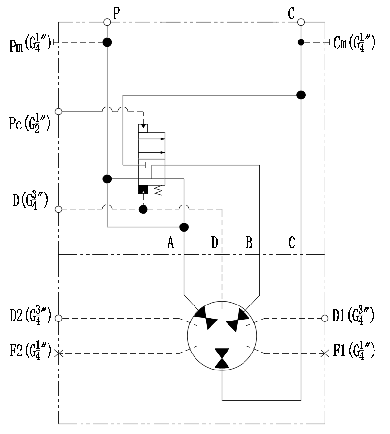
The shifting mechanism relies entirely on the VTCA two-speed valve. This valve acts as the critical control hub for the motor. It receives a pilot pressure signal from the operator cabin or machine controller. Upon receiving this signal, the valve shifts its internal spool. This action redirects hydraulic fluid to engage or disengage specific piston banks.
Effectively, the valve halves the motor's displacement. By cutting the displacement in half, the motor consumes half as much fluid per revolution. If the pump flow remains constant, the motor spins twice as fast. However, because only half the pistons are pushing against the cam ring, the torque output drops by half. This inverse relationship is the core mechanical trade-off of the system. The VTCA valve must handle this transition smoothly to prevent severe hydraulic shock from damaging the motor internals.
This architecture provides two distinct operational modes. Engineers map these modes to specific machine functions to optimize performance across the entire duty cycle.
Mode 1 (Full Displacement): The motor utilizes all available pistons. This provides maximum torque. Machines use this mode for starting under heavy loads, digging into dense material, or climbing steep grades. Speed is relatively low, but pulling power is immense. The full surface area of all pistons reacts against the system pressure.
Mode 2 (Reduced Displacement): The VTCA valve disengages half the pistons. The motor shifts into high speed. Machines use this mode for rapid transit across a job site. It allows equipment to reposition quickly or return an empty attachment to the starting position. It utilizes the exact same pump flow as Mode 1, preventing the need for a larger primary pump.
Field engineers frequently face a common sizing dilemma. A machine lacks the power to turn a heavy load. The initial thought is to upgrade from a 34cc motor to a 65cc motor. Installing a larger fixed motor certainly increases torque. However, the mathematical reality is harsh. If the primary pump's GPM remains constant, doubling the motor size cuts the rotational speed in half. The machine gains power but becomes painfully slow. You cannot cheat fluid dynamics; volume dictates speed.
A 2-speed system solves this exact problem. It offers two distinct displacement options without requiring a massive primary pump upgrade. You get the torque of a 65cc motor for heavy work. You get the speed of a 32cc motor for travel. You bypass the need to install larger hoses, bigger directional valves, and a higher-capacity diesel engine. This dual capability allows engineers to size the primary pump for the continuous working load rather than the peak transit speed.
Technical Parameter | Fixed Displacement Motor | 2-Speed CA Hydraulic Motor |
|---|---|---|
Torque Output | Constant and highly stable | Variable (High in Mode 1, Low in Mode 2) |
Speed Range | Limited by maximum pump flow | Extended (Doubles speed in Mode 2) |
Pump Size Requirement | Large (to achieve both torque and speed) | Small to Medium (optimized for dual modes) |
System Complexity | Low (Basic 2-line plumbing) | High (Requires VTCA valve and pilot lines) |
Space Claim | Minimal footprint | Slightly larger due to shifting manifold |
Heat Generation | High at maximum flow rates | Lower due to optimized displacement usage |
Volumetric efficiency measures how much fluid leaks internally past the pistons. Mechanical efficiency measures how much energy is lost to physical friction. Fixed motors generally have excellent mechanical efficiency at their rated speeds. However, their overall system efficiency drops in variable applications. When you force a fixed motor to spin faster than its optimal design parameter, fluid friction creates severe heat.
A dual-displacement motor allows engineers to specify a smaller primary hydraulic pump. The motor achieves high speeds without requiring massive flow rates. This smaller pump consumes less engine horsepower. It generates less heat. The entire hydraulic circuit operates closer to its peak efficiency curve. By matching the motor's displacement to the immediate load requirement, the system avoids dumping excess fluid over the relief valve.
Physical space requirements dictate many design choices. CA motors are inherently compact. Their radial piston design fits well inside wheel hubs, winch drums, and track drives. However, adding the two-speed valve requires specific plumbing. You must allocate manifold space. You must route pilot pressure lines from the main control block to the motor. This requires careful engineering in tight spaces.
This contrasts with the straightforward plumbing of a fixed motor. A fixed system only requires an A port, a B port, and a case drain. The 2-speed setup demands more careful hose routing to prevent rubbing and failure. The pilot lines are typically small-diameter hoses (1/4 inch or 3/8 inch) that are susceptible to external damage if not properly shielded. Engineers must design protective guards to shield these critical control lines from debris.
Heat generation destroys hydraulic fluid. Fixed motors running at high speeds require high flow. Pushing 50 GPM through a motor designed for optimal efficiency at 25 GPM creates severe fluid friction. The oil temperature spikes. Viscosity breaks down. When viscosity drops, internal leakage increases, further reducing the motor's efficiency in a destructive cycle.
Dual-displacement motors mitigate these high-flow heat issues. They achieve high speeds with lower flow rates. However, they introduce localized heat considerations. Frequent shifting forces fluid through the tight clearances of the shifting valve. This creates localized pressure drops. Engineers must size the case drain lines generously to flush this heat away from the motor housing. A restricted case drain will trap hot oil inside the motor, leading to premature bearing failure and seal degradation.
Certain applications heavily favor fixed displacement designs. You should specify them for applications with narrow, predictable load-speed profiles. If the machine requires a fixed rate of liquid flow and pressure, keep it simple. Adding complexity where it is not needed only increases the risk of downtime.
Stationary Industrial Equipment: Augers, industrial mixers, and standard rotary drives operate under steady loads. They do not need a travel mode. The load remains constant for hours at a time.
Continuous Winches: Marine and industrial winches that pull at a constant rate benefit from stable, unwavering torque. The operator needs precise control over the line pull without sudden shifts in speed.
Harsh Environments: Applications where external damage to pilot lines is highly likely. Forestry mulchers operating in dense brush often rip off external hoses. Fewer hoses mean fewer failure points.
Simplicity Requirements: Systems where reducing maintenance complexity overrides the need for cycle-time optimization. Remote mining sites often prefer fixed motors because they are easier to troubleshoot without specialized diagnostic equipment.
High-variance duty cycles demand flexibility. Upgrading becomes necessary when a machine performs two completely different tasks during its operational cycle. If a machine spends more than 20% of its time tramming or repositioning, a single-speed motor severely limits productivity.
Mobile Tracked Equipment: Excavators, skid steers, and forestry equipment. They need massive torque to push dirt or climb hills. They need high speed to travel across the site. A two-speed drive is mandatory for competitive performance.
Space and Weight Optimization: Applications where reducing the primary pump size yields significant space savings. A smaller pump allows for a smaller diesel engine, reducing the overall weight of the machine.
Throughput Optimization: Scenarios where rapid cycle times directly correlate to increased productivity. Returning a drill head to the surface quickly saves minutes per hole. Over a full shift, this translates to significant operational gains.
Heavy-Duty Mobile Crushers: Machines that require intense starting torque to clear jammed material, but benefit from faster transit speeds when repositioning around the quarry.
Introducing shifting mechanisms introduces new failure points. The most common issue is valve spool sticking. The internal spool relies on incredibly tight tolerances to prevent internal leakage. If contamination enters the system, the spool can jam. The motor may become stuck in high speed or high torque. Pilot pressure failures also occur. If the pilot line leaks or the signal pressure drops below the required threshold (typically 200-300 PSI), the valve will not shift completely. This causes partial engagement, leading to rapid internal wear as fluid bypasses the half-shifted spool.
Shifting under heavy load presents another risk. While many valves are designed for dynamic shifting, doing so under peak pressure creates hydraulic shock. This shockwave travels through the system, stressing hoses and seals. Operators should ideally reduce the load momentarily before engaging the transit mode. Training operators to lift the machine's blade or bucket before shifting extends the life of the motor significantly.
Protecting the sensitive tolerances of the two-speed valve requires rigorous filtration. You cannot operate these systems with dirty oil. Standard fixed motors might tolerate an ISO cleanliness code of 21/19/16. A 2-speed system demands much cleaner fluid. You must maintain an ISO cleanliness code of at least 18/16/13. This requires high-quality return line filters.
It also requires dedicated kidney-loop filtration systems on larger machines. Water contamination must remain below 500 ppm to prevent corrosion on the shifting spool. Even microscopic rust particles will score the valve bore, causing internal leakage that prevents the motor from holding high torque. Mechanics must take oil samples regularly to verify fluid health.
Retrofitting a 2-speed system into an existing fixed-displacement circuit requires careful engineering. You cannot simply bolt the new motor in place. You must establish pilot pressure availability. The system needs a dedicated, stable pressure source to shift the valve. You must integrate the control system. This involves wiring an electrical switch in the cabin to a solenoid valve, which then sends the hydraulic pilot signal down to the motor.
Case drain sizing is critical. The case drain line must be large enough to handle the internal leakage from both the motor pistons and the shifting valve. If the case drain line is too small, pressure builds up inside the motor housing. This blows out the main shaft seal, causing catastrophic fluid loss. Case pressure must typically remain below 35 PSI. When retrofitting, mechanics often make the mistake of teeing the case drain into a standard return line. Return lines experience pressure spikes during cylinder actuation. These spikes travel backward into the motor case. You must route case drains directly to the reservoir, terminating below the fluid level to prevent aeration.
The decision between a dual-displacement system and a fixed alternative hinges entirely on the variance in the machine's duty cycle. High variance demands flexibility. Low variance favors simplicity and stable torque. If the ratio of transit time to heavy-load working time exceeds 20%, the dual-displacement setup is structurally superior. It prevents the need for massive, oversized primary pumps while delivering the exact performance required for each phase of operation.
To ensure successful implementation, follow these next steps:
Conduct a comprehensive duty-cycle analysis to map out exactly how much time the machine spends in transit versus heavy work.
Calculate the absolute maximum starting torque required to prevent stalling under the worst-case load scenario.
Evaluate your existing hydraulic circuit to confirm you have a stable pilot pressure source available for the shifting mechanism.
Upgrade your return-line filtration system to meet the strict ISO cleanliness codes required by precision spool valves.
Consult with a hydraulic systems engineer to accurately size the displacement ratios and ensure the case drain plumbing can handle the increased flow.
A: A 2-speed CA motor uses a stepped design, shifting between two specific displacement volumes. A variable displacement motor uses a swashplate to continuously adjust the volume across an infinite range between its minimum and maximum settings.
A: The valve receives a pilot pressure signal and shifts an internal spool. This blocks hydraulic fluid from reaching half of the motor's internal pistons. With only half the displacement volume to fill, the constant pump flow spins the motor twice as fast.
A: Displacement directly dictates both. If you increase the motor's displacement while keeping pump flow constant, your torque increases, but your rotational speed decreases proportionally. Decreasing displacement increases speed but sacrifices torque.
A: No. A fixed displacement motor lacks the internal fluid galleries and dual piston banks required for shifting. You must completely replace the fixed motor with a dual-displacement motor and install the necessary control valves and pilot lines.
A: While designed to handle dynamic shifts, shifting under peak load creates severe hydraulic shockwaves. Frequent shifting under maximum pressure accelerates wear on the valve spool and internal seals. Operators should momentarily reduce the load before shifting.
A: Torque is a function of displacement and pressure. When shifted into high speed, the valve disengages half of the internal pistons. Because only half the pistons are pushing against the mechanical cam ring, the total rotational force is cut in half.